Before calibration, ensure that all sensors are thoroughly cleaned and inspected, including the removal of sensor covers to confirm that there are no obstructions. Do not proceed with sensor calibration unless they have been cleaned properly, this will otherwise cause detection issues.
Do not calibrate without cleaning your sensors first!
For the calibration itself, you have two methods from which you can choose.
Method A: Remote Calibration
The following is the easier way to calibrate you sensors, but it only works if
-
you have at least controller firmware 3.1.3 (click here to get details on how to update)
-
it's not the first-time calibrating your system at it's current location
You can perform the calibration remotely by pressing "Start calibration" at Settings -> Sensors -> Sensor calibration.

Method B: On-site Calibration
This method always works, but is a lot more effort.
Step 1 | Open the console
What you need
- A ladder (not a straight one, it should stand by itself to keep the detection area of the wall unobstructed)
- A TX30 Torx screwdriver (for the console cover)

- Remove the screws (M6, TX30 Torx) of the console. Depending on the generation, it will be two to six screws.
- Pull at the lower end of the cover to detach it from the rest of the frame. The upper end is secured by a tab. Lift the cover upward to remove it.
Step 2 | Calibrate the sensors
What you need
- A small flat screwdriver (for the DIP switches)
Please make sure that nothing touches the wall within the sensor frame. No ladder or cables or other obstacles that could interfere with the sensors. The total frame needs to stand clear.
On the right-hand side of your console, you will find either two or four of the following devices (the controllers), depending on the version of your system.

Recalibration Process

For all texts in bold, please refer to the image above
- Power off all controllers using the power switches underneath.
- Make sure no objects are between the sensors.
- For each controller (①, ② and if you have ③, ④), repeat:
-
- Switch the little DIP 3 - the second little switch from the top - to the left (ON position)
- Power the controller on, using the power switch underneath the controller
- ⚠ Wait for five seconds ⚠
- Switch DIP 3 to the right (OFF position)
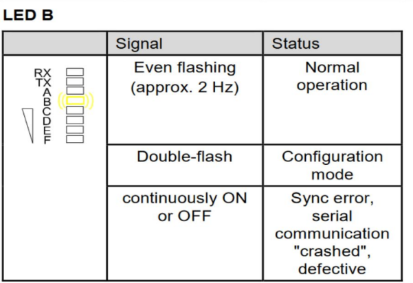
- Check that the calibration is ok:
- LED B blinks in a steady interval
- LED C or D or E is on, LED F is off
It’s fine if the light jumps from one to the other - LED OUT 1 turns on only if you touch the wall
- Power off the controller; repeat from 1 with the next controller
- Power on all controllers, using the power switches underneath

Troubleshooting
In cases where one of the red lights (as shown in the following diagram) is on, it is probable that either one of the light bars or the controller is faulty.


You will find additional information here.
How to find out what exactly is broken?
If one controller is fine and the other has the red lights, the easiest test to narrow down is to swap the light bars.
- Always power off controllers during changing cabling
- Connect the light bars from the left controller to the right one and vice versa.
- Redo the calibration (as described above).
- If the error stays with the light bars that is where the problem lays, if it stays with the controller this one is bad.
If you need to trace down further on the light bars, only connect one pair each time and redo the calibration
Probably one pair will work and another won't. You can then change the sender or receiver from the faulty pair to find out which side of the faulty pair is not working.
Once you have defined the faulty element, replace it or contact the LYMB.iO support for replacement parts.